- 您现在的位置:买卖IC网 > Sheet目录3855 > PIC18LF1330-I/SO (Microchip Technology)IC PIC MCU FLASH 4KX16 18SOIC
PIC18F1230/1330
2009 Microchip Technology Inc.
DS39758D-page 103
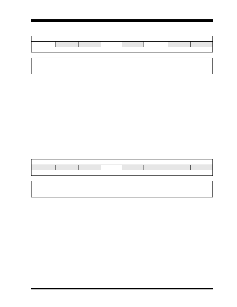
REGISTER 11-11: IPR2: PERIPHERAL INTERRUPT PRIORITY REGISTER 2
R/W-1
U-0
R/W-1
U-0
R/W-1
U-0
OSCFIP
—
EEIP
—LVDIP
—
bit 7
bit 0
Legend:
R = Readable bit
W = Writable bit
U = Unimplemented bit, read as ‘0’
-n = Value at POR
‘1’ = Bit is set
‘0’ = Bit is cleared
x = Bit is unknown
bit 7
OSCFIP:
Oscillator Fail Interrupt Priority bit
1
= High priority
0
= Low priority
bit 6-5
Unimplemented:
Read as ‘0’
bit 4
EEIP:
Data EEPROM/Flash Write Operation Interrupt Priority bit
1
= High priority
0
= Low priority
bit 3
Unimplemented:
Read as ‘0’
bit 2
LVDIP:
Low-Voltage Detect Interrupt Priority bit
1
= High priority
0
= Low priority
bit 1-0
Unimplemented:
Read as ‘0’
REGISTER 11-12: IPR3: PERIPHERAL INTERRUPT PRIORITY REGISTER 3
U-0
R/W-1
U-0
—
—PTIP
—
bit 7
bit 0
Legend:
R = Readable bit
W = Writable bit
U = Unimplemented bit, read as ‘0’
-n = Value at POR
‘1’ = Bit is set
‘0’ = Bit is cleared
x = Bit is unknown
bit 7-5
Unimplemented:
Read as ‘0’
bit 4
PTIP:
PWM Time Base Interrupt Priority bit
1
= High priority
0
= Low priority
bit 3-0
Unimplemented:
Read as ‘0’
发布紧急采购,3分钟左右您将得到回复。
相关PDF资料
ATMEGA32-16AI
IC AVR MCU 32K 16MHZ IND 44-TQFP
ATMEGA32-16MI
IC AVR MCU 32K 16MHZ IND 44-QFN
ATMEGA32-16PI
IC AVR MCU 32K 16MHZ IND 40-DIP
ATMEGA32-16AC
IC AVR MCU 32K 16MHZ COM 44-TQFP
ATMEGA32-16MC
IC AVR MCU 32K 16MHZ COM 44-QFN
ATMEGA32-16PC
IC AVR MCU 32K 16MHZ COM 40-DIP
06FMN-BMTTN-A-TF
CONN FMN HSNG 6POS STAG NOR SMD
05FMN-BMTTN-A-TF
CONN FMN HSNG 5POS STAG NOR SMD
相关代理商/技术参数
PIC18LF1330-I/SS
功能描述:8位微控制器 -MCU 8KB Flash 256byteRAM 16 I/O8-bit Family RoHS:否 制造商:Silicon Labs 核心:8051 处理器系列:C8051F39x 数据总线宽度:8 bit 最大时钟频率:50 MHz 程序存储器大小:16 KB 数据 RAM 大小:1 KB 片上 ADC:Yes 工作电源电压:1.8 V to 3.6 V 工作温度范围:- 40 C to + 105 C 封装 / 箱体:QFN-20 安装风格:SMD/SMT
PIC18LF13K22-E/ML
功能描述:8位微控制器 -MCU 8KB Flash 256byte RAM 256byte EEPROM
RoHS:否 制造商:Silicon Labs 核心:8051 处理器系列:C8051F39x 数据总线宽度:8 bit 最大时钟频率:50 MHz 程序存储器大小:16 KB 数据 RAM 大小:1 KB 片上 ADC:Yes 工作电源电压:1.8 V to 3.6 V 工作温度范围:- 40 C to + 105 C 封装 / 箱体:QFN-20 安装风格:SMD/SMT
PIC18LF13K22-E/P
功能描述:8位微控制器 -MCU 8KB Flash 256byte RAM 256byte EEPROM
RoHS:否 制造商:Silicon Labs 核心:8051 处理器系列:C8051F39x 数据总线宽度:8 bit 最大时钟频率:50 MHz 程序存储器大小:16 KB 数据 RAM 大小:1 KB 片上 ADC:Yes 工作电源电压:1.8 V to 3.6 V 工作温度范围:- 40 C to + 105 C 封装 / 箱体:QFN-20 安装风格:SMD/SMT
PIC18LF13K22-E/SO
功能描述:8位微控制器 -MCU 8KB Flash 256byte RAM 256byte EEPROM
RoHS:否 制造商:Silicon Labs 核心:8051 处理器系列:C8051F39x 数据总线宽度:8 bit 最大时钟频率:50 MHz 程序存储器大小:16 KB 数据 RAM 大小:1 KB 片上 ADC:Yes 工作电源电压:1.8 V to 3.6 V 工作温度范围:- 40 C to + 105 C 封装 / 箱体:QFN-20 安装风格:SMD/SMT
PIC18LF13K22-E/SS
功能描述:8位微控制器 -MCU 8KB Flash 256byte RAM 256byte EEPROM
RoHS:否 制造商:Silicon Labs 核心:8051 处理器系列:C8051F39x 数据总线宽度:8 bit 最大时钟频率:50 MHz 程序存储器大小:16 KB 数据 RAM 大小:1 KB 片上 ADC:Yes 工作电源电压:1.8 V to 3.6 V 工作温度范围:- 40 C to + 105 C 封装 / 箱体:QFN-20 安装风格:SMD/SMT
PIC18LF13K22-I/ML
功能描述:8位微控制器 -MCU 8KB Flash 256byte RAM 256byte EEPROM
RoHS:否 制造商:Silicon Labs 核心:8051 处理器系列:C8051F39x 数据总线宽度:8 bit 最大时钟频率:50 MHz 程序存储器大小:16 KB 数据 RAM 大小:1 KB 片上 ADC:Yes 工作电源电压:1.8 V to 3.6 V 工作温度范围:- 40 C to + 105 C 封装 / 箱体:QFN-20 安装风格:SMD/SMT
PIC18LF13K22-I/P
功能描述:8位微控制器 -MCU 8KB Flash 256byte RAM 256byte EEPROM
RoHS:否 制造商:Silicon Labs 核心:8051 处理器系列:C8051F39x 数据总线宽度:8 bit 最大时钟频率:50 MHz 程序存储器大小:16 KB 数据 RAM 大小:1 KB 片上 ADC:Yes 工作电源电压:1.8 V to 3.6 V 工作温度范围:- 40 C to + 105 C 封装 / 箱体:QFN-20 安装风格:SMD/SMT
PIC18LF13K22-I/SO
功能描述:8位微控制器 -MCU 8KB Flash 256byte RAM 256byte EEPROM
RoHS:否 制造商:Silicon Labs 核心:8051 处理器系列:C8051F39x 数据总线宽度:8 bit 最大时钟频率:50 MHz 程序存储器大小:16 KB 数据 RAM 大小:1 KB 片上 ADC:Yes 工作电源电压:1.8 V to 3.6 V 工作温度范围:- 40 C to + 105 C 封装 / 箱体:QFN-20 安装风格:SMD/SMT